Documentation for items offered on the site.
ROMulator 6502
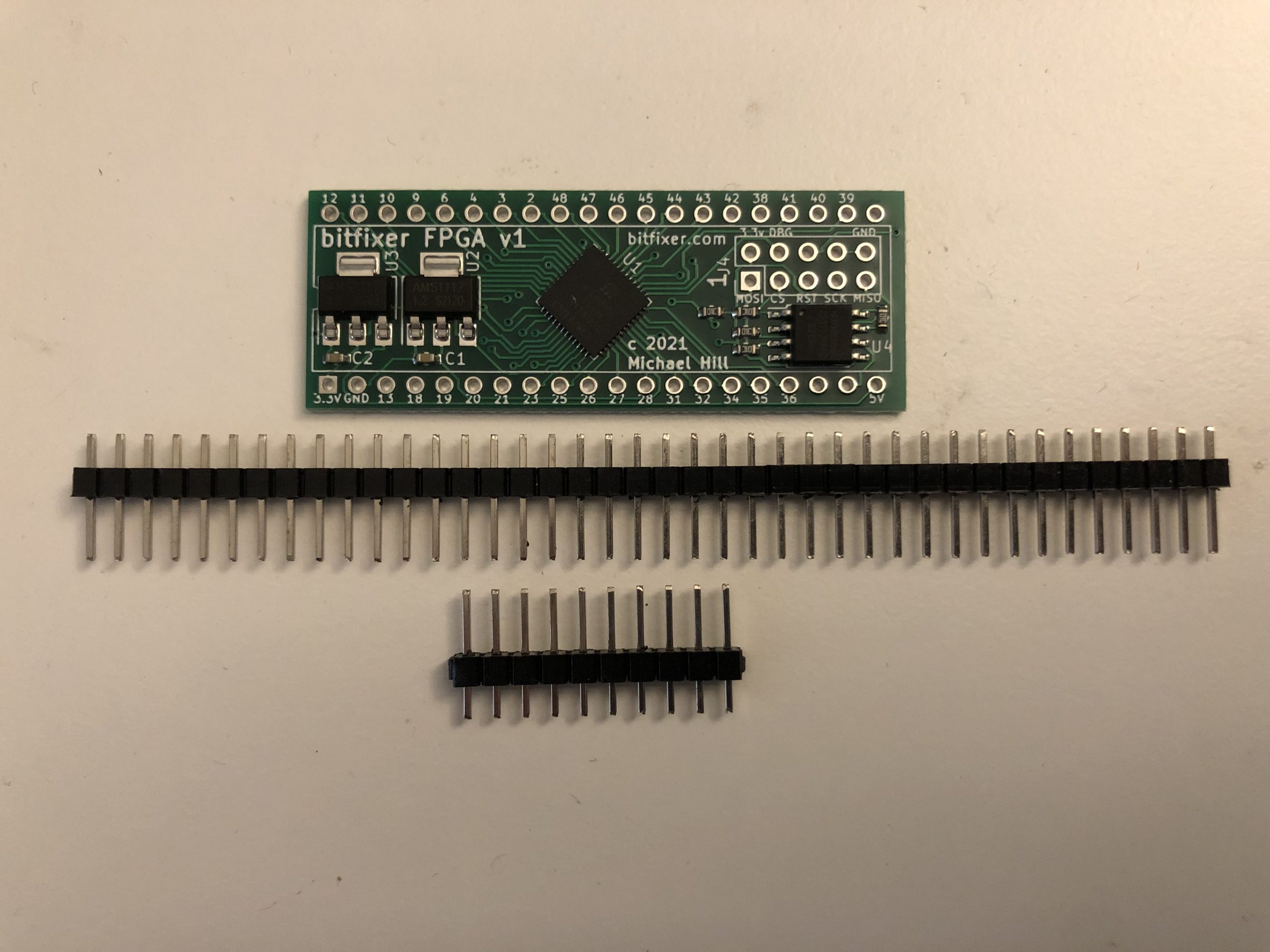
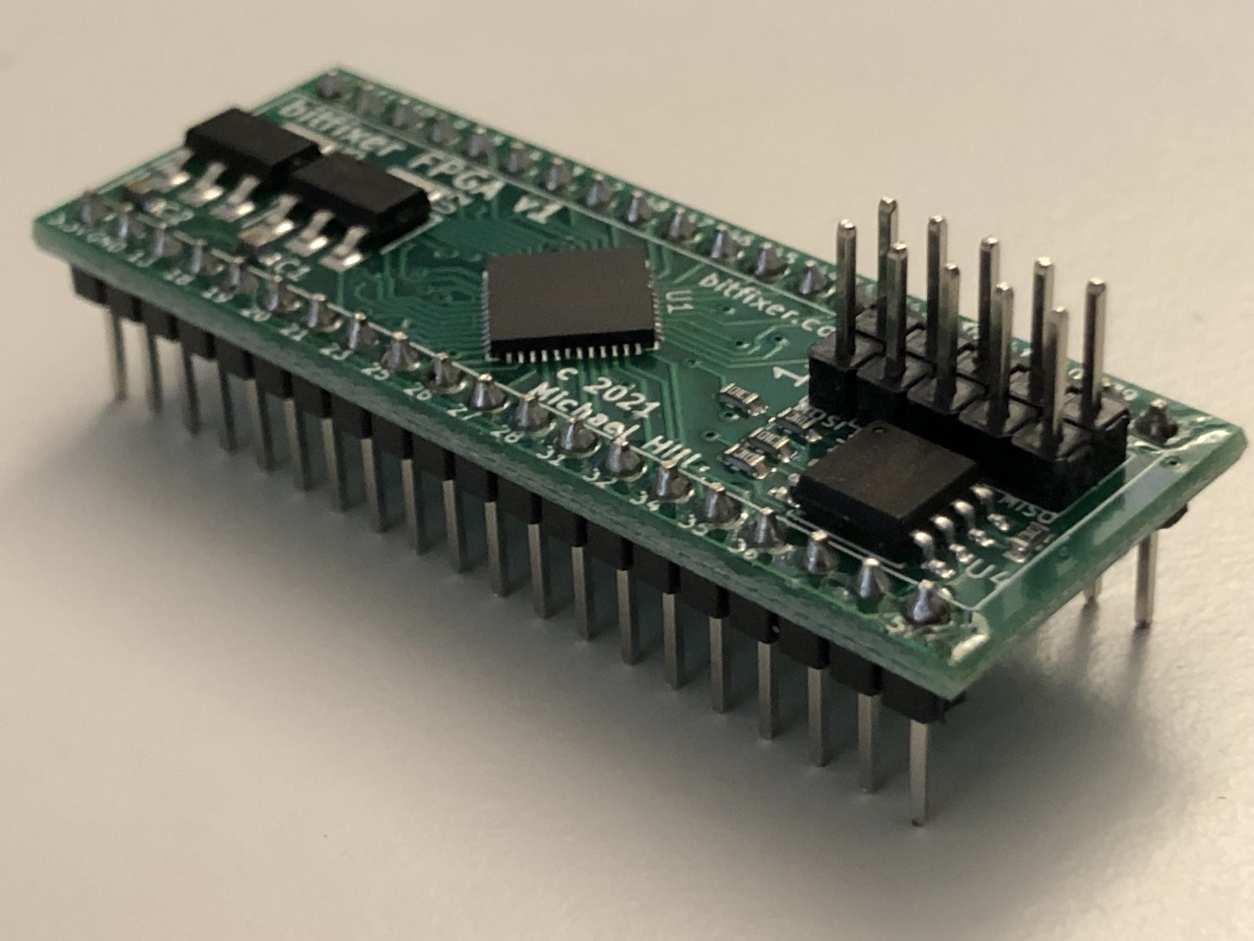
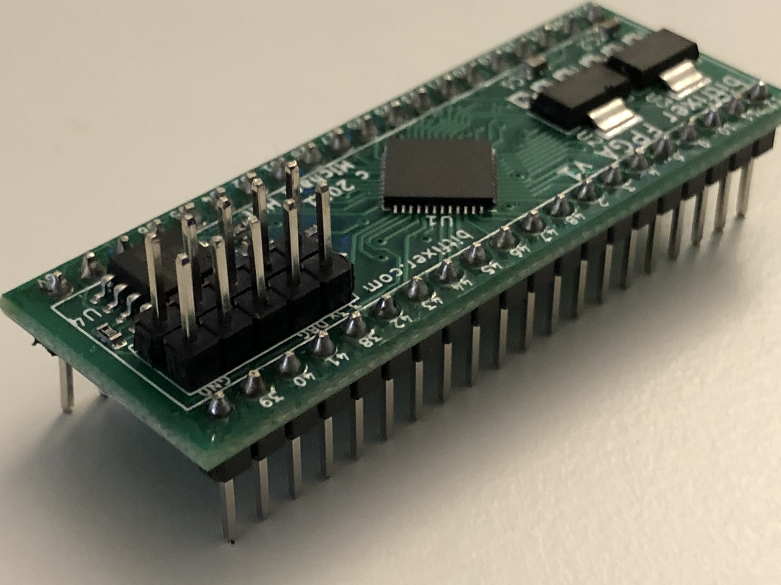
ROMulator Assembly InstructionsFirst, please check if your FPGA board already has pin headers soldered on.
If not, solder on 2x 20 pin headers and 2x 5 pin headers as shown:
|
|
|
More information in the ROMulator GitHub Repo
ROMulator Z80
Thank you for being one of the first people to try out the ROMulator Z80!Please see the instructions for ROMulator 6502 for assembly and setup.
The FPGA board for the ROMulator Z80 currently comes un-programmed. You will need to program it before use with either a Raspberry Pi or the standalone programmer kit which includes a D1 Mini.
The only differences from the 6502 version include:
- edit the files ‘config/memory_set_default_z80.csv’ and ‘config/memory_set_default_z80.csv’ to modify configurations.
- run ‘make romulator_z80’ instead of ‘make romulator’ to build the z80 version of the firmware
- run ‘make program_z80’ instead of ‘make program’ to both build and program the device.
Documentation for the ROMulator Z80 will be added to the github readme as time allows.
PETdisk MAX v2
Note (1/2): Depending on availability, you may have received an edge connector with pins (top) or wider wire terminals (bottom).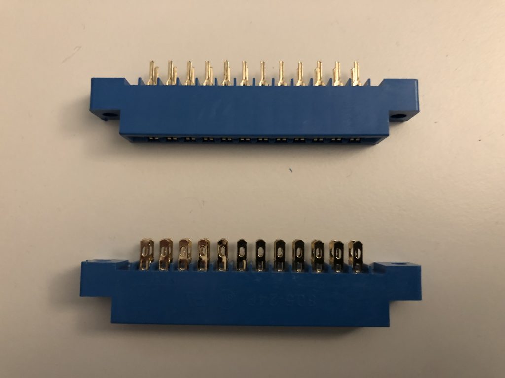
The PETdisk board accommodates either, but if you have the version with pins, try to center the pins in the board slots. The assembly video shows the version with wire terminals.
Note (2/2): Please check if your kit contains this 1×8 socket:
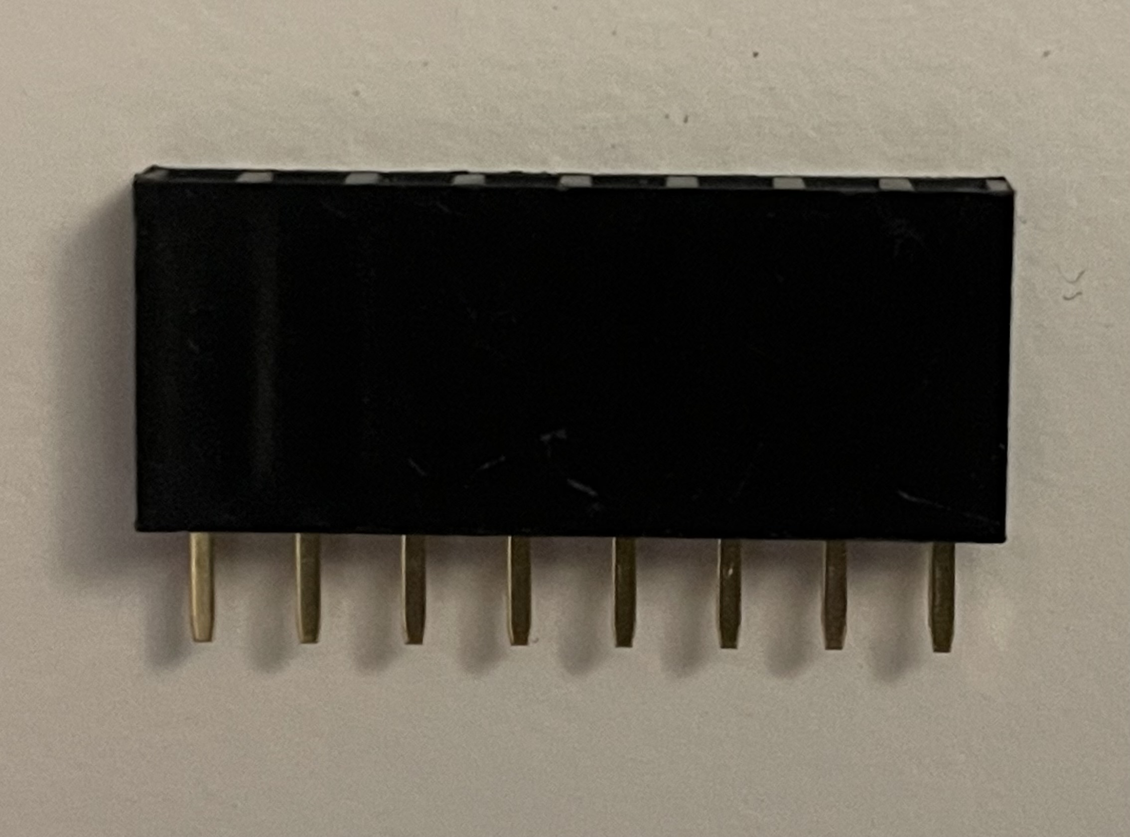
If you have this socket, continue with the assembly as shown in the video below. If not, your kit will contain a 1×2 pin header and clip lead with socket as shown here:
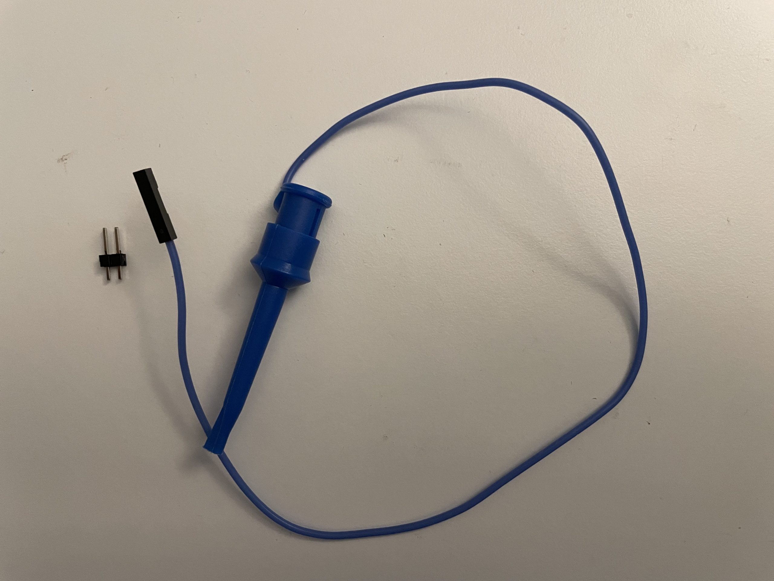
Proceed with the assembly as shown in the video except instead of soldering on the 1×8 socket, solder the 1×2 pin header into the positions marked “NC” and “5V”. The back of the board will look like this:
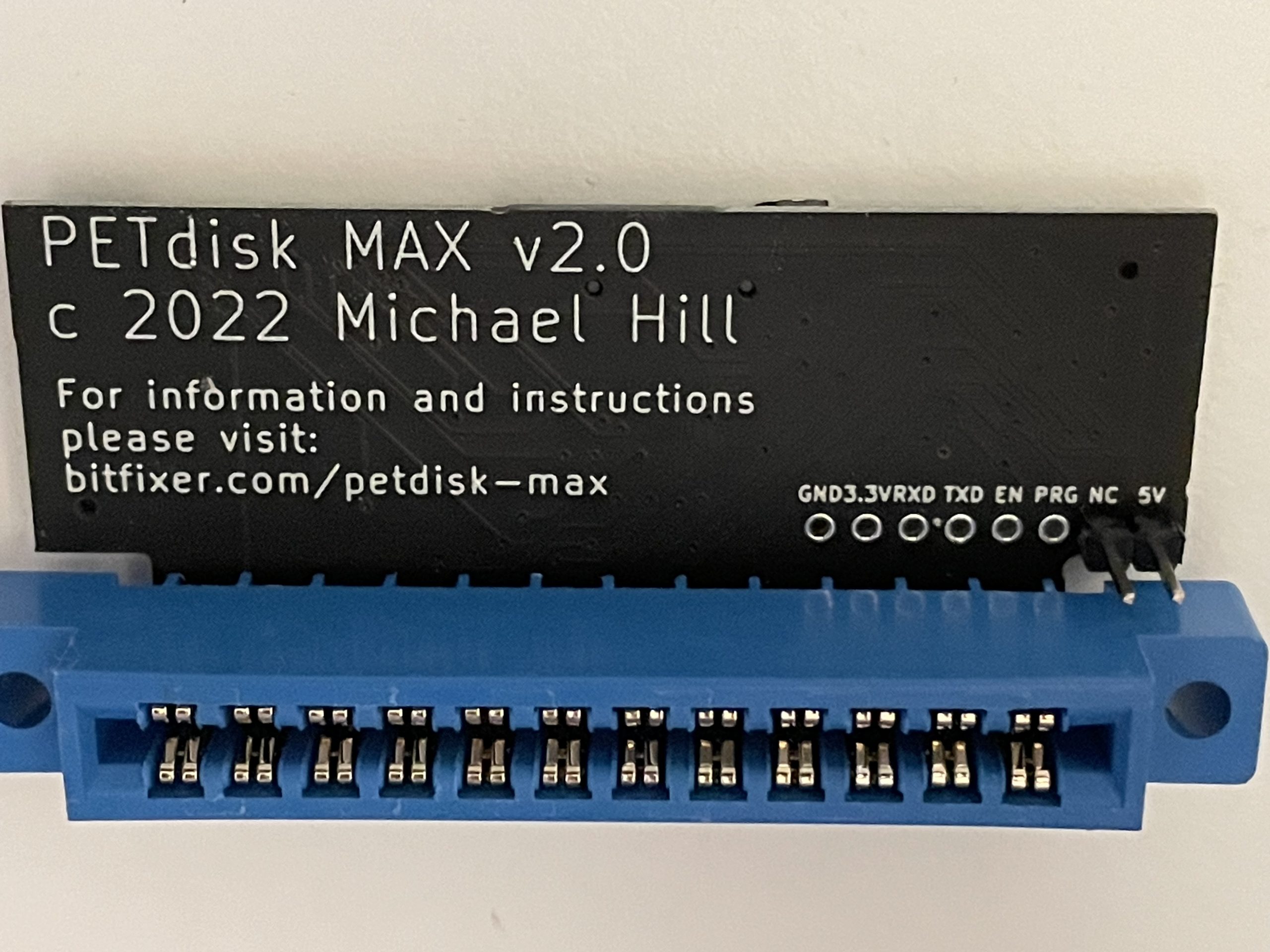
When powering the device from the clip lead, attach the socket at the end of the wire to the “5V” pin. The rest of the assembly instructions are the same as shown in the video below.
PETdisk Max v3
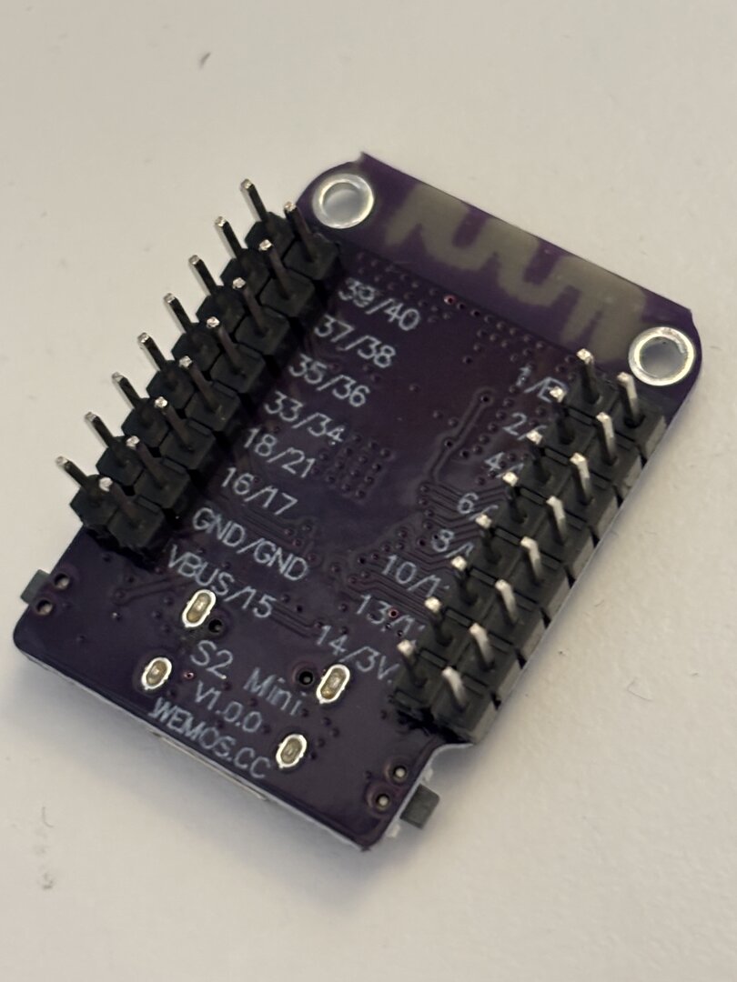
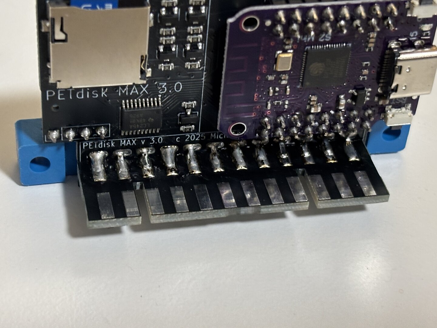
link Assembly video coming soon!Step 1: Solder 4 1×8 headers onto the S2 Mini board as shown:
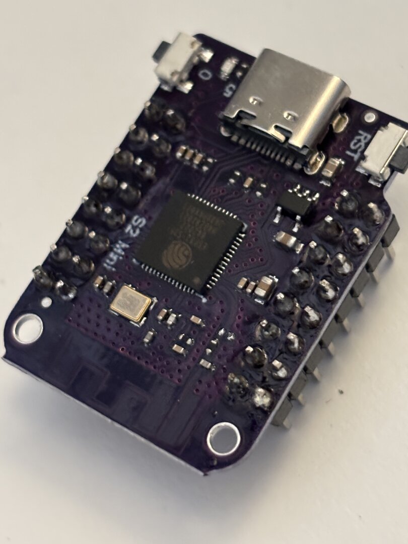
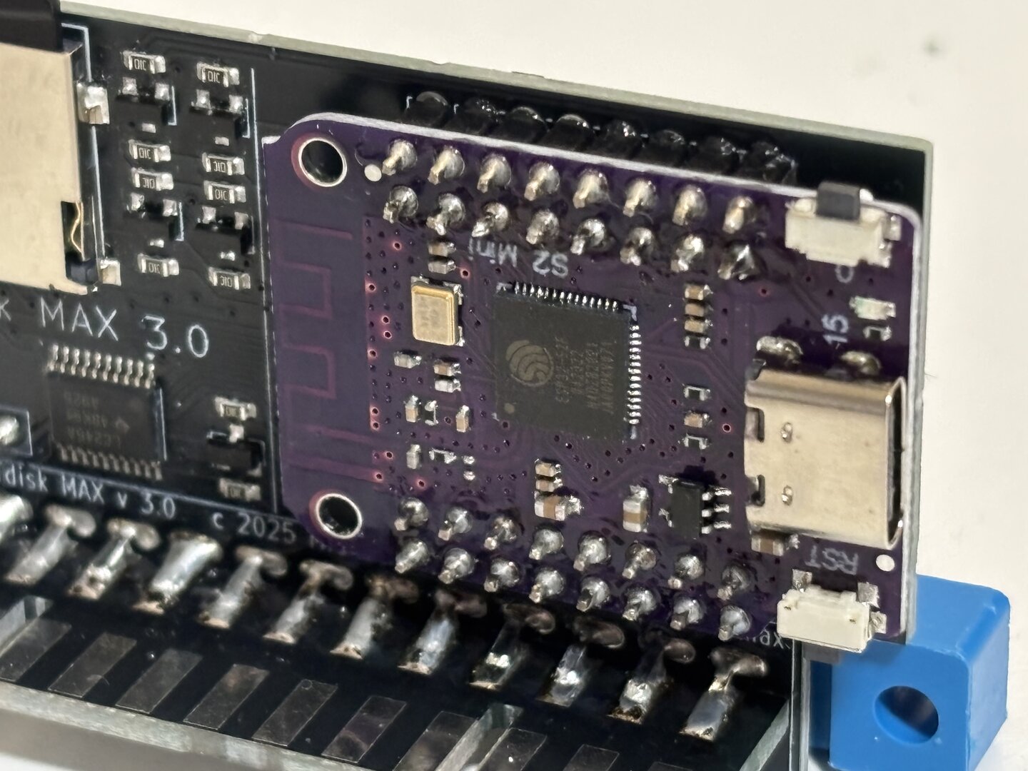
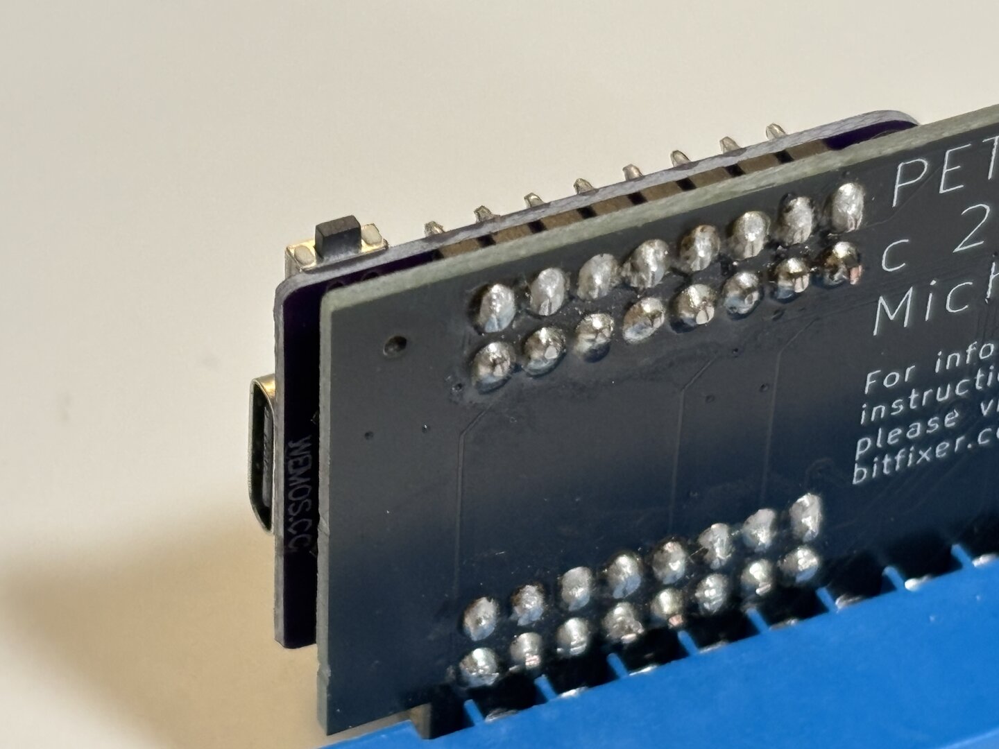
Step 2: Solder S2 Mini with headers onto main Petdisk board. Note the direction of the USB-C connector. Clip the pins on the back after soldering as shown.
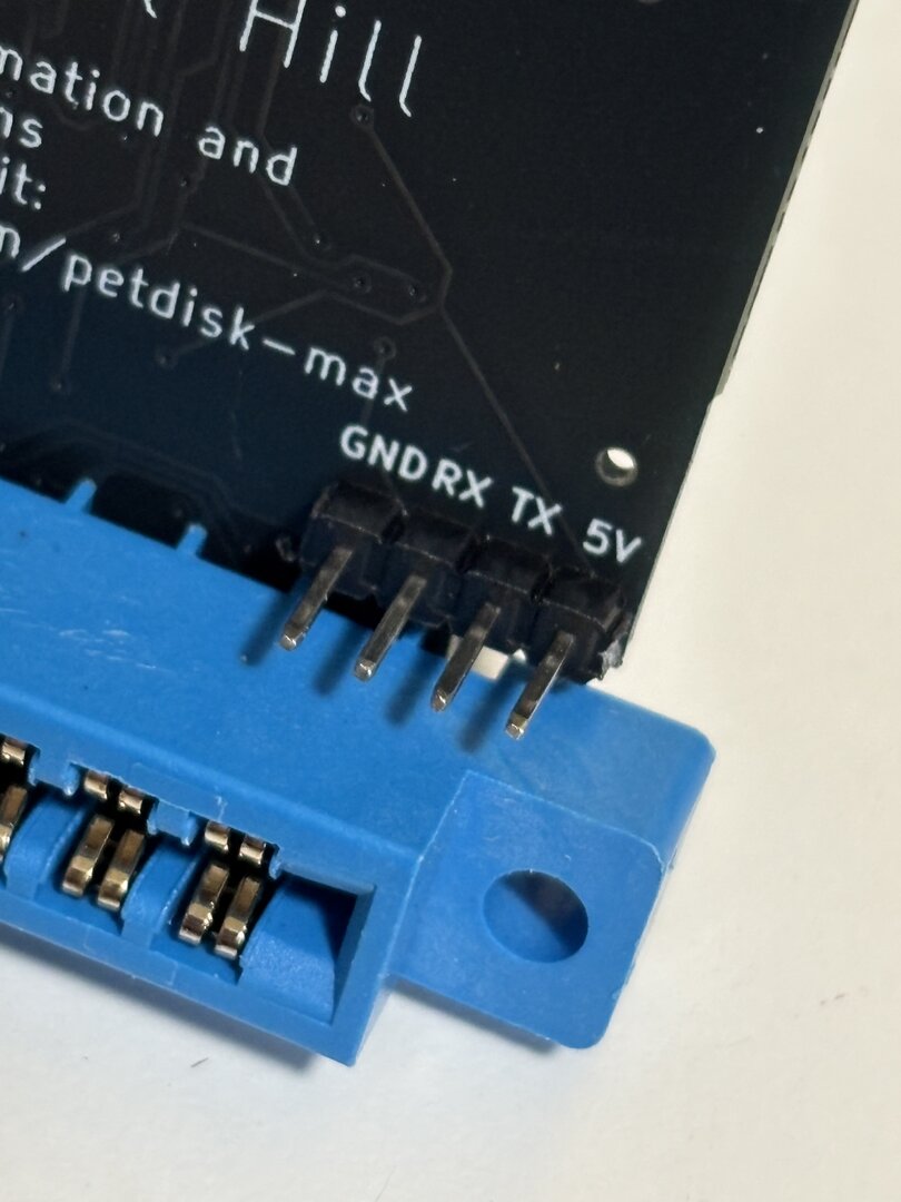
Step 3: Solder 4 pin header, check board side
Step 4: Solder edge connector (note what side of the board as shown)
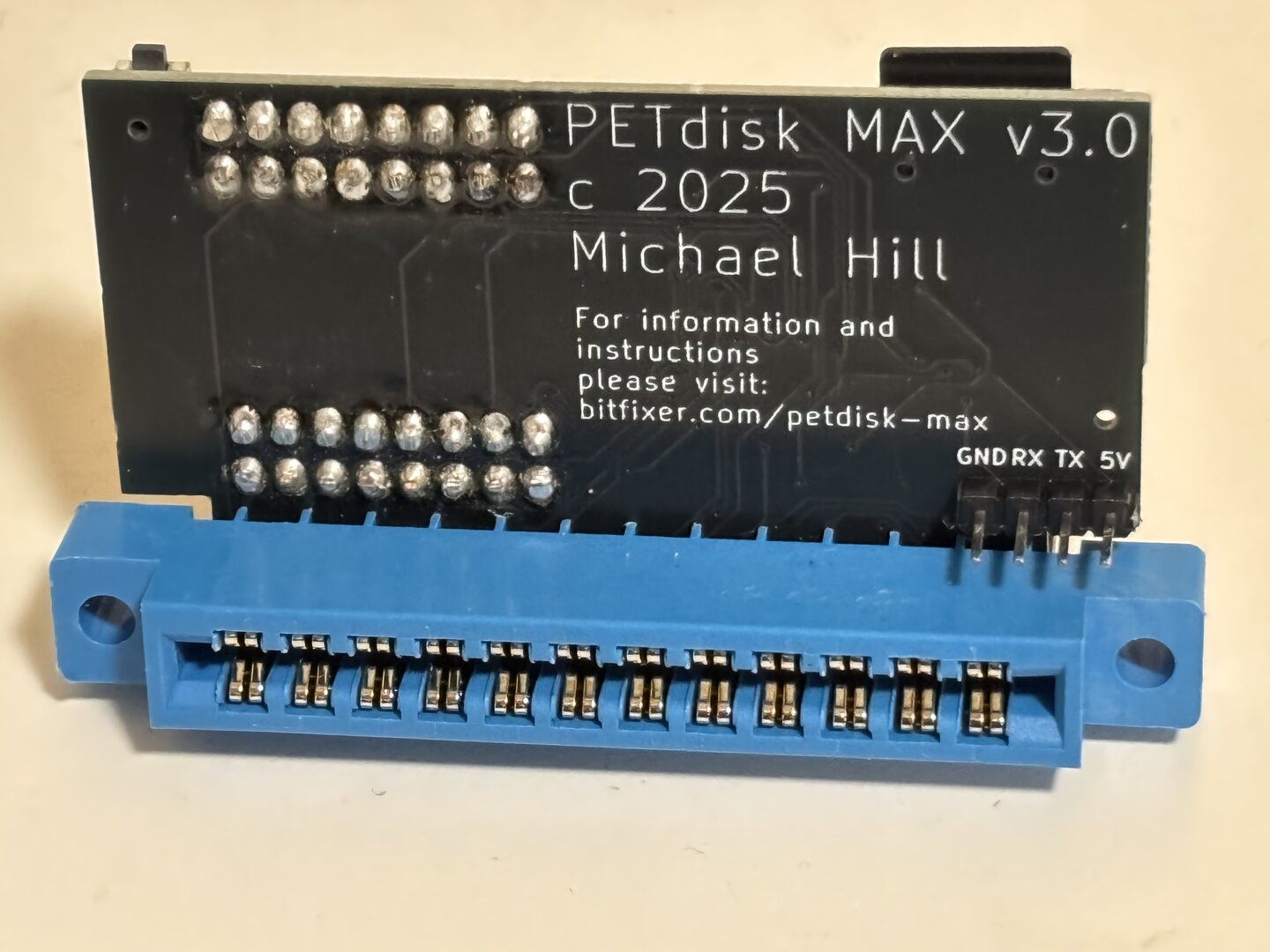
Step 5: Solder the PCB connector extension – note the slot locations in the image.
Installation
Plug the PETdisk MAX v3 to the IEEE-488 port on the pet. Take the clip lead provide, and clip onto pin 20 of the 6520 chip in the PET. This is +5V. Connect the socket end to the +5V pin on the petdisk max.
PETdisk MAX v2: Assembly and Operation
PETdisk MAX v1 Kit Assembly
More information in the PETdisk MAX GitHub Repo
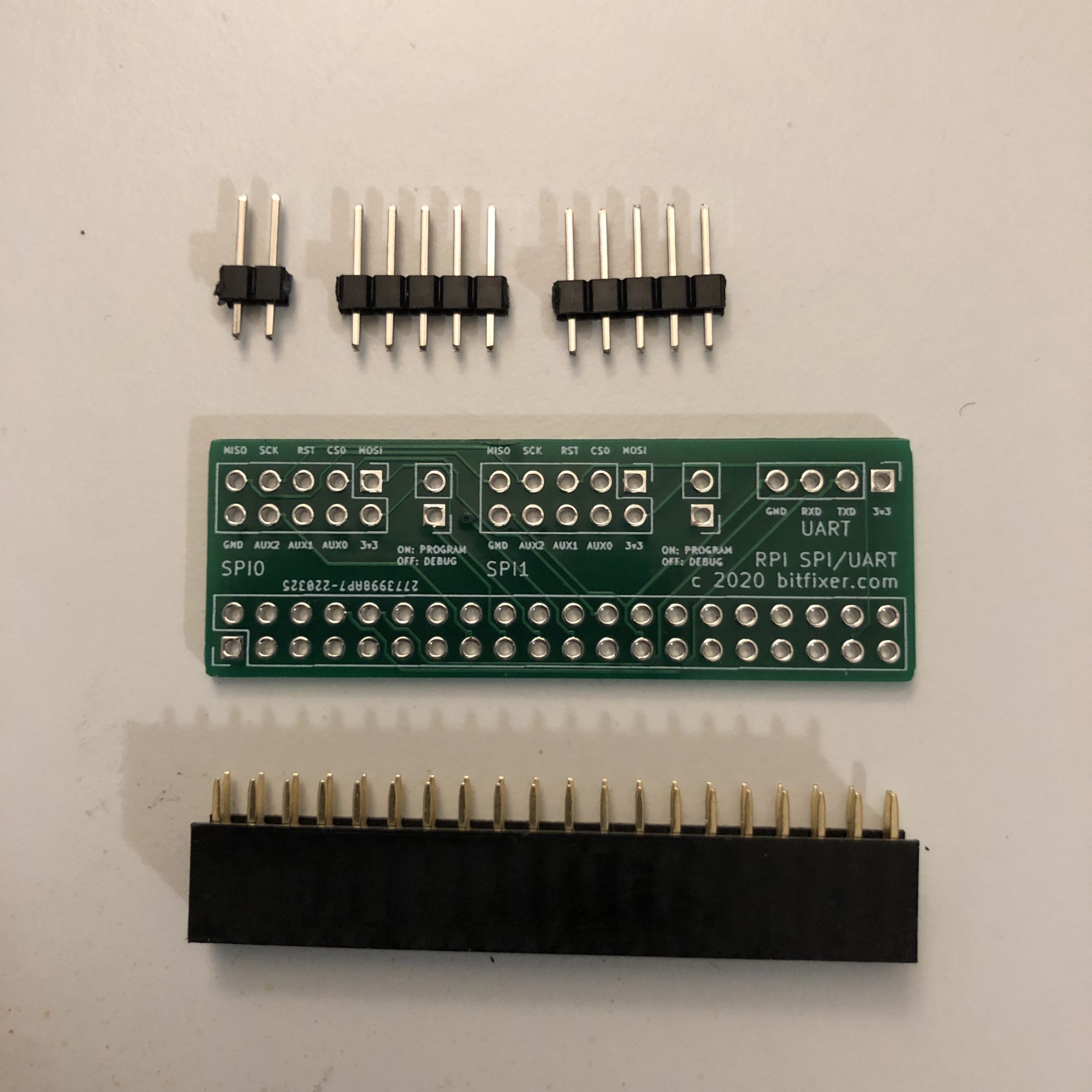
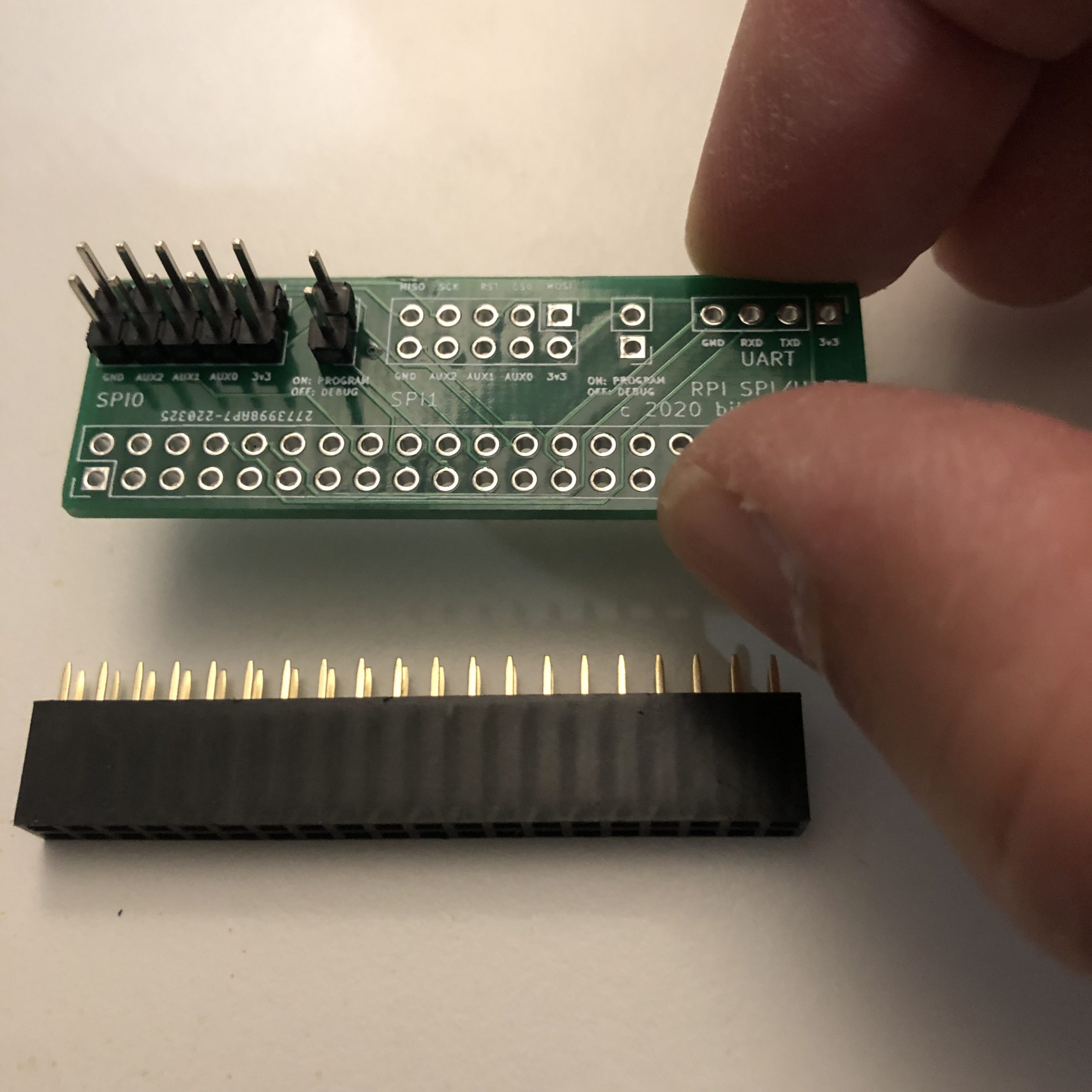
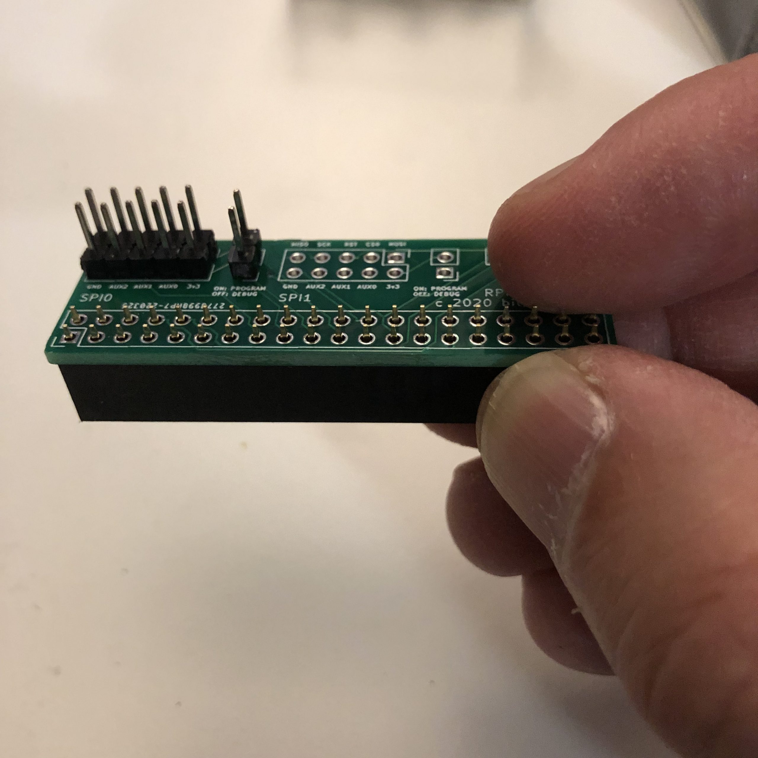
Raspberry Pi SPI/UART Breakout
Assembly: Solder 2×5 pins on the ‘SPI0’ section of the board. Also solder a 1×2 pin header to the position next to SPI0. Then solder the 2×20 female socket on the bottom of the board. See images for details. The remaining positions on the board do not need to be populated to program/debug with the ROMulator, they do provide optional access to the second SPI port (SPI1) on the Raspberry Pi, as well as the serial port (UART).
|
|
|